Design, Implementation, and Application of a Tool for Optimal Aircraft Positioning
J. Pfalzgraf 1, K. Frank 1, J. Weichenberger 1, S. Stolzenberg 2
Abstract
Optimal positioning of aircraft at a specific airport is a very difficult problem involving the modeling of many constraints. Lufthansa AG stated this problem field for the airport Frankfurt/Main. We are presenting an approach consisting of two main parts. The development of a generic airport model (independent of Frankfurt) where the notion of logical fiberings plays a basic role. The optimization task is treated by applying modified and extended genetic algorithms. A system has been implemented which can compute positioning plans which can be used by the human operator for further processing. This leads to a considerable speed up in generating plans for aircraft positioning in contrast to the former system. The application of the positioning tool to a real world scenario is briefly presented.Keywords: optimal aircraft positioning, logical fiberings, genetic algorithms, hybrid problem solving
1 Introduction
This contribution deals with the general problem of optimal positioning of aircrafts at an airport. The problem formulation has been provided by Lufthansa AG for the concrete airport Frankfurt/Main. The main task in the field of aircraft positioning is to find an optimal schedule for all incoming and outgoing aircrafts with respect to their position at corresponding gates of an airport. One has to take into account many constraints and requests, such as neighborhood relationships, runway crossings, critical passenger connections, aircraft types, airline requests, special gates, security constraints, and others, depending on particular situations. The basic task is to fulfill all these constraints and requests in an optimal way so that the yield converges to a predefined maximum. . Our work consists of two main parts. The development of a ``generic airport model'' not depending on the choice of a specific airport - and thus reusable - and the application of extended and modified genetic algorithms to work on the optimization problem. A rather complicated fitness function (cost function) has been developed in cooperation with Lufthansa. In establishing the airport model, the concept of logical fiberings plays a basic role. This is a logical modeling approach which allows to describe what we call the logical state space of a virtual airport (distribution of logics). Thus for example a gate and a position has its own ``local'' logic and they can communicate via non-classical logical operations called transjunctions. In principle it would be possible to apply methods from multi-agent systems (MAS). In our case a gate or an airplane position could be interpreted as an agent, respectively. Instead, we model on basis of the concept of logical fiberings (each agent corresponds to a ``local fiber''). Application of MAS techniques is intended future work. For the of the optimization problem we use modified and extended genetic algorithms. A special suitable fitness function has been devised which encodes the basic information and constraints underlying the positioning task. The system has been implemented. A detailed description of the generic airport model, the evolutionary optimization approach, the system design and real world applications can be found in [FW99].
As far as we know no such approach to treat the problem field as described above has been tried before. This has been confirmed by somebody from the EvoNet project. And no such implemented system existed before, as Lufthansa states. There is a considerable increase of perfromance by our system in comparisonto the procedure used so far. Our PC-based system needs about one hour to calculate a positioning plan which can then be used by a human operator to process it further. In contrast to that, with the former mthod, the human planner needed about one week to establish a similar plan ``by hand'' supported by a graphical computing system, interactively.
2 On logical fiberings
The purpose of this section is twofold: to give a very brief introduction to the elementary notions of logical fiberings for later use and to bring them to the attention of the reader. The concept of logical fiberings originates in an industrial project - a case study on so-called polycontextural logics and their potential application to model complex communication and information systems logically. Subsequently we present only the elementary notion of a logical fibering and point to practical applications in the area of cooperating agents (in particular cooperating robots) scenarios. A detailed introduction to logical fiberings with background information and motivating comments can be found in [Pfa91].
The notion of a logical fibering is inspired by the mathematical modeling language of fiber bundles. This very expressive and powerful notion integrates different structures, namely geometric, topological, and algebraic structures. A fiber bundle consists of a whole bunch of fibers which form a so-called total space ditributed over a base manifold. Each fiber is mapped via a projection map onto its base point in the base space. Thus, for example, in a vector bundle the typical fiber is a vector space of a given dimension. So we can say that in a fiber bundle vertically one does algebra and horizontally geometry, topology.
Concerning a logical fibering now the idea is to use a fiber bundle and take logics as fibers, thus, vertically one does logic. In [Pfa91] we take as typical fiber a classical two valued logic. Thus a logical fibering is an abstract fiber space (or bundle) with typical fiber F = L, a classical first order logical space or a subspace generated by a set of formulas. The base space B of the fibering will often be denoted by B = I, the indexing set, the total space is denoted by E, and p: E � I is the corresponding projection map. For i � I we have the fiber p-1(i) over i, namely p-1(i) = {x � E | p(x) = i} it has the structure of a logic as mentioned above. We note that E is decomposed into the fibers p-1(i) for all i � I.
The simplest form of a fibering is the "trivial fibering" having total space E = I ×L, base space I and p(i,l) = i. Therefore the fiber over i � I is Li : = p-1(i) = {i} ×L. Such a trivial fibering is a ``parallel system'' of logics Li over the index set I as base space. We can think of reasoning processes running in parallel within each fiber Li = p-1(i). A fiber Li is interpreted as a local logical system (a subsystem of the whole fibering). Transition (communication) betweeen fibers is described with the help of suitable maps (cf. [Pfa91]). Such a trivial fibering as previously considered will also be called "free parallel system" with total space the disjoint union of the fibers Li. Each subsystem Li has local classical truth values Wi = {Ti,Fi}. The global set of truth values is denoted by WI. In a free parallel system WI is just the disjoint union of the Wi for i � I.
Logical connectives can be introduced by taking "fiberwise" logical operations. For example, one can form logical expressions like the following for a system with three fibers (using vector notation): (x1 �y1, x2 � y2, x3 �(�y3)), etc.. For more details we refer to [Pfa91].
A special nonclassical bivariate operation arises naturally: a local pair (xi,yi) in Li ×Li, i � I, can be mapped into different subsystems La, Lb,.... Taking truth values as input we can observe that for the four possible input pairs in Wi ×Wi for a locally defined bivariate operation there can be maximally four different subsystems where that function can be evaluated. We can say that the values will be distributed over the subsystems. Such an operation is called transjunction. Below we give an example of a ``conjunctional'' transjunction - we just display the truth table
|
Every transjunction can be described by such a table or ``T-F-pattern'' together with the indices {a,b,g,d}. If {a,b,g,d} � {i} then we obtain a transjunction - in the previous example we have the type of a conjunction as can be seen by omitting the indices. If {a,b,g,d} = {i} then we have a classical conjunction remaining in subsystem Li.
We applied transjunctions for the logical control of cooperating robots scenarios. Cf.[Pfa97] for a brief discussion of such an application. For further information on the subject we refer to [PSS96a], [PSS96b]. In the framework of this contribution here we apply methods from logical fiberings to support logically the modeling of the aircraft positioning system as described subseqently.
We consider the concept of logical fiberings as a natural logical modeling approach for multi-agent systems. This has been discussed in [Mei99]. Future work is intended, especially with respect to planned work on an extended generic airport model.
3 An approach for treating the positioning problem
3.1 Design concept of the positioning tool
First of all, we want to give a short problem description and what we mean by aircraft positioning. The main task of aircraft positioning is to find schedules for all incoming and outgoing aircrafts at an airport. Difficult constraints have to be considered, like runway crossings, (optimal) passenger connections, aircraft types, special flights, particular gates, airline requests, security problems, and others. The main problem in the field of aircraft positioning is to find an optimal schedule for all incoming and outgoing aircraft with respect to their positions and corresponding gates. Three subtasks have to be distinguished: long-time, short-time and the actual day scheduling. To each subtask corresponds an individual knowledge about the aircraft which influences the positioning. The knowledge changes rapidly during scheduling. The external state of the airport can change rapidly, for example, caused by construction work. Thus an important design objective is to build a tool which is able to react to rapidly changing situations. As previously mentioned, we decided to choose logical fiberings as a logical modeling approach. This decision was naturally motivated by our problem analysis. Figure 1 shows the global system design.
|

Our system includes various agencies and data areas, namely the kernel agency, the airport agency and the external data areas, like airport database, temporary flightplan. Another part of our system is the output unit and the output communication unit, which will be used to visualize an airport utilization.
The communication between the various parts of our tool will be handled by a negotiation protocol in the final version. This allows us to handle the basic communication tasks in our system during the short-time planning task. The complete tool will handle two other states, the long-time planning task and the actual day.
3.2 External data areas
The external data areas are specialized data storages for, e.g airport description, flight characteristics, airport characteristics , airline characteristcs and something similar to these characteristics. We use an airport database, which includes basic airport information, like the number of positions and gates. Moreover, the infoserver, which is our main data source for flight information, the airline preferences, the flight specialities and the gate and position specialities. All these areas contain positioning relevant data, which are necessary to calculate an optimal solution for the positioning problem.
3.3 Airport Agency
The airport agency is used to model a virtual airport. The virtual airport is identical to an existing airport, in our case the Rhine-Main airport. The design of the virtual airport is based on the concept of logical fiberings. The airport agency, respectively the virtual airport, consists of serveral units, two units are interfaces for communication with the enviroment and all others are internal units, which are used to create the virtual airport. First, there is the precalculating filtering hierarchical list of positions and gates (p.f.H.L.P.G) and second the output communication unit (O.C.U), which will not be discussed in this contribution, these two units manage the data transfer with the enviroment and prepare input data for the internal use in the airport agency and the kernel agency, which will be decribed later in this contribution. Figure 2 gives an overview of the design of the airport agency with their units and the internal communication paths.
|

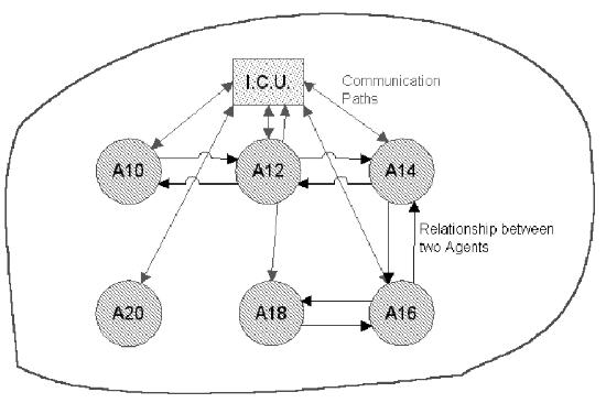
The airport agency, shown in Figure 2, includes a number of virtual clusters, e.g. ''AWEST'', ''AOST'' or ''BWEST''. These clusters include the fibers of our airport. We use two different types of fibers one for positions and the other one for gates because they have a lot of different characteristics. Some typical characteristics of a position fiber are the maximum valid wing code or the buffertime, on the other side some typical characteristics of a gate fiber are the maximum number of allowed passengers in the gate area or the time to bring the passengers to the aircraft.
In terms of logical fiberings to each ``agent'' corresponds a ``local'' fiber. These fibers are connected via communication paths with the p.f.H.L.P.G. and they can have further connections to their neighbors. The connections (communication) with neighbors are modeled by transjunctions. A transjunction can be used to control the state space of neighbored (connected) fibers. The special effect in an application of a transjunction can be as follows: if local fiber A corresponds to, for example, an aircraft or group of passengers (GoPax), and there is a transjunction from A to fiber B, then the state space of fiber B will be downgraded by the transjunction. The downgrade of the state space of fiber B will be cancelled as soon as fiber A is no longer used by (``attached to'') an aircraft or GoPax.
Example:Transjunction rule 'A10' to 'A12'
if 11 then 5
The effect of this transjunction is, that the state space of 'A12' will be downgraded to SWC 5, if the current SWC of 'A10' is 11.
Here SWC is the short notation for ``wing code''. One has to take into account that different wing codes have to be distinguished - there exist priorities which must be taken into consideration.
Figure 3 shows a special cluster with its communication paths and neighborhood relationships. Moreover, the complexity of the state space of each agent depends on the number of allowed aircraft types for each agent. That is why the absolute complexity could reach a value which is greater or equal to n (n is currently 50).
|
3.4 Kernel Agency
The kernel agency includes currently 4 different algorithms, the adaptive long-time scheduling algorithm, the genetic short-time scheduling algorithm, the random scheduling algorithm, the conflict solving algorithm. Also part of the kernel is the kernel communication unit. In this contribution we discuss the genetic short-time scheduling algorithm, the other scheduling algorithms are planned as future work or are not of scientific interest (random scheduler).
3.4.1 Genetic short-time scheduling algorithm
This genetic algorithm [Mic96], [Hof96] is designed to solve the problems occurring in short time scheduling. It takes an already pre-optimized season plan (generated by a human or using a long time scheduler) together with actual changes and additions (including actually flying passengers, available planes, passengers that need to get a connection and many more). We decided to use evolutionary computing to solve this problem as the prerequisites are suitable for such an algorithm. If the season plan is already optimized, we can expect that it contains many building blocks, which a genetic algorithm (GA) can use and thus find an optimal solution faster. The prerequisites also look promising when using some sort of evolutionary strategies. As the precalculated solution of the long time scheduler should provide promising areas such an algorithm can work to improve the solution. However there are many problems using a classical GA, which will be described in the next paragraph.
The first idea was to solve the problem using a normal genetic algorithm, encoding the positions of the given aircraft in a standard way (figure 4).
|
While this approach works it causes one important problem: almost no valid (valid for a final solution) individuals get created this way, since most solutions will position one of the planes either on an impossible position (plane is too large, for example) or it will position planes at the same time on the same position. Of course such solutions would get a very low fitness, so they are not likely to produce offspring. Still we get the problem that the resulting algorithm spends most of the time searching for a solution where the planes actually fit and not for an optimal pattern of the planes, wasting valuable time.
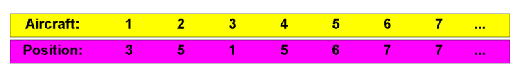
So another approach was taken. First we changed the coding such that now the aircraft get mapped onto positions (figure 5).
|

This enables us to use the complete rule set already which are provided by the airport agency. So we are now able to allow only such genetic operators that produce a valid individuum and not all possible operations. For example, if the aircraft number one would be a B747 and the only positions that can hold such a plane would be positions one, two and three, then a mutation on plane number three could only mutate it towards position one, two, or three. Still, given the elegance of the first representation it is present as well in form of a hash table for faster access of the data.
While this second model works very well with the mutation operator, unfortunately it raises new problems when using a crossover operator. Namely the probability of data loss or the duplication of data. Both these problems are very well known as they also occur when trying to find solutions for a travelling salesman problem with the help of GAs.
So when doing a crossover not only the parts that are actually selected get exchanged, but also other parts to maintain consistency. To do so we have to check for each exchanged plane if its counterpart is also moved. If not we have to set this aircraft also on the exchange list. On the first view this seems to be a very useful trick to solve the problem, but it also produces a problematic side-effect. Every time we wish to do a crossover at a certain point we also exchange planes on quite randomly chosen other positions. While this is not wanted in a GA (aesthetically) it also can destroy building-blocks, especially in a problem as big as the positioning task. For this reason we decided to not implement a crossover operator in the classical way. However there are operators that work quite similar.
The Condense Operator (Mutation 1)
The goal of this simplest mutation operator is to get all planes in the other section of the airport on valid normal positions. To achieve this goal three main steps are needed. First, all planes in the other section are taken into the Temp area. Then one or more randomly chosen aircraft that were already positioned are also assigned to this Temp block. Finally the random scheduler is called to order all available planes into the airport.
The Replace Operator (Mutation 2)
This second mutation operator is almost as simple as the first one, but works in the opposite way. It is mainly used to keep the diversity in a population. To do this it moves a plane from one position to another one. Technically this is also done in three steps. First one aircraft gets randomly selected. This aircraft gets on the Temp place. Then the algorithm selects randomly a position where the plane could fit.''Could'' in this context means the algorithm checks if the plane fits if the position were free, but does not check if it is free. Then the selected plane is force-positioned on the selected position, this means it gets positioned there in all cases, removing disturbing planes if necessary. Such planes get dropped into the other area, where they can be reordered using the random scheduler.
Chromosome Repositioning (Mutation 3)
This is the last and most 'advanced' mutation operator that will be used in this implementation of the GA. It does not operate on single planes like the other two, but on complete positions. The idea behind this is that there might be a very good positioning, but it is on the wrong position (good time intervals, but not at the terminal for example). So what this operator does is that it selects a position. Then it takes all planes of this position to the Temp area. Next a second, similar position is selected. Similar is a wide term, but in this context we mean a position that has quite the same attributes like the first one (size for example). Then also all planes of this position are carried over to the Temp part. Finally all planes of the first position are assigned to the second one and vice versa as possible.
Guided Replace (Crossover 1)
Before we explain how this operator works some notes are included that are valid for all crossover operators. As explained earlier there can arise many problems when using crossover operators in the given problem. Thus we decided to not use them in a classical way, but in a form of a new class of genetic operators. This class works as a mixture between crossover and mutation. It behaves like a normal crossover (and so we prefer still to use this name for it) functionally, but it has a probability of occurrence like a mutation. So this crossover operators could also be seen as guided mutations. By using this system we still get the benefits of the crossover operators that work on the building blocks we have, while we try not to destroy too many other building blocks. We only exchange small blocks and not the half of the genetic material (on average).
The Guided Replace operator is the first and simplest of these operators. It simply does move a chosen plane in individual 1 at the position this plane had in individual 2 and vice versa. The operation itself works like all others in three main steps shown in the graphics. The first step is the selection of one aircraft. This aircraft gets removed from both individuals and gets stored on the Temp area. Together with this information we also have to store on which position the plane was on each airport interpreted as an individuum. In the next step we force-position these planes back into the corresponding airports, but with exchanged positions. In the ideal case we are done at this point, but naturally this operation causes other planes to drop into the other position, which get reordered into the airports in step 3 with the use of the random scheduler.
Guided Chromosome Repositioning (Crossover 2)
This crossover-like operator works similar to the mutation operator with the same name. The idea behind it is to transfer a perfect distribution of planes on one position in one individual into another individual. The same works, of course, for the other direction. Here we face the problem mentioned earlier, so the exact algorithm becomes a quite complicated ruleset in 4 steps. First a position is selected (the same in both individuals). All aircraft on these positions get dropped on the Temp field, noting their former individual. If we would simply position them now in the other individual we would get the problem of vanishing planes, so we need the second step that takes the planes that were removed in one individual also from the second individual. The only difference to the first step is that these individuals get positioned into the other field. The next step of the operator puts the planes in the Temp area back to their original position, switching between airport 1 and airport 2. Finally, the remaining planes of airport 1 get ordered into airport 2 using the random scheduler and also the other way around.
Cluster Crossover (Crossover 3)
This is the most advanced crossover operator. As the airport contains groups of positions it was plausible to also group these for the optimization process as it is very likely that the connections within one cluster are already quite good and should be used as building blocks. On the other hand this operator is quite destructive with respect to other regions and should therefore be used with a rather low probability. The internal algorithm behind this function is directly connected to the second crossover operator, in fact we can use this operator for the cluster crossover if we simply select more than one position (all positions in the given cluster) instead of the one position of the original function.
Fitness Function
To find an appropriate fitness function was one of the main problems of the complete optimization process. Not only are there many factors that are important for creating an optimal plan, also flexibility was one of the key goals. It had to be possible to only optimize to some of the given factors and not to all.
Given the current complexity the formula is divided over several functions. The main function F(i) is divided into 4 different main optimization criteria for an individual i:
Hereby P(i) denotes the part that tries to optimize the number of passengers. C(i) is responsible for reducing the connecting time. S(i) describes the service aspects and Q(i) the quality of the solution.
The passenger part takes care that a maximum amount of passengers can leave or enter a plane directly from the gate (IP and OP). Additionally also the yield of the passengers can be taken into account (IY and OY). P(i) also optimizes that a maximum amount of aircraft are positioned right in front of the building (IB and OB)
The connexe (connecting passengers) part optimizes the time needed to get from one plane into the other. To do so two options are possible. Either the buffer time (maximal possible time to reach plane - walking time) is maximized (CT) or special gates are used for planes with many connecting passengers (GD)
S(i) denotes the service part of the fitness function. I tries to make the positioning of the planes as comfortable as possible for the passengers. Three factors are summarized here. BN and BY reduce the amount of bus transfers or respectively the amount of bus transfers for valuable passengers. The third factor, PD, ensures that the time between boarding and take off is as small as possible.
Finally Q(i) takes care that the solution is a possible solution at all. PC and GC take care that all positions and gates are valid ones, while CC ensures that all connecting passengers are able to catch their planes
4 Application of the tool to a real world scenario
5 Conclusions
In the previous sections we presented work on the hard problem of optimal positioning of aircraft at an airport. Many real world constraints have to be considered. The original problem has been described by Lufthansa AG focusing on airport Frankfurt/Main. We developed a general (generic) airport model using, among others, the concept of logical fiberings. The optimization problem was treated by modified and extended genetic algortihms. On the basis of these approaches an aircraft positioning tool was developed and implemented especially tailored for computing positioning configurations of the airport Frankfurt/Main. A prototypic first version of the system is currently being tested with Lufthansa at Frankfurt airport. Our new system achieves much better performance than the methods applied before.
In addition to the previously described methods, in future work we intend to use also methods from artificial neural networks (for modeling position constraints and optimization), make systematic applications of multi-agent systems techniques, and ruled based systems.
References
- [FW99]
-
K. Frank and J. Weichenberger.
Design and implementation of an aircraft positioning tool using
hybrid problem-solving methods.
Master's thesis, Institut für Computerwissenschaften, Universität
Salzburg, Austria, 1999.
- [Hof96]
-
Frank Hoffmann.
Automatischer Entwurf von Fuzzy-Reglern mit genetischen
Algorithmen.
PhD thesis, Mathematisch-Naturwissenschaftliche Fakultät,
Christian-Albrechts Universität zu Kiel, Germany, 1996.
- [Mei99]
-
W. Meixl.
Logical fiberings. a general decomposition method for many-valued
logics and a modeling approach for multi-agent systems.
Master's thesis, Institut für Computerwissenschaften, Universität
Salzburg, Austria, 1999.
- [Mic96]
-
Zbigniew Michalewicz.
Genetic Algorithms + Data Structures = Evolution Programs.
Springer-Verlag Berlin Heidelberg, 1996.
- [Pfa91]
-
J. Pfalzgraf.
Logical fiberings and polycontextural systems.
In Fundamentals of Artificial Intelligence Research, Ph.Jorrand,
J.Kelemen (eds.). Lecture Notes in Computer Science 535, Subseries in AI,
Springer Verlag, 1991.
- [Pfa97]
-
J. Pfalzgraf.
On geometric and topological reasoning in robotics.
Annals of Mathematics and Artificial Intelligence, 19:279-318,
1997.
- [PSS96a]
-
J. Pfalzgraf, U. Sigmund, and K. Stokkermans.
Towards a general approach for modeling actions and change in
cooperating agents scenarios.
special issue of IGPL (Journal of the Interest Group in Pure
and Applied Logics), IGPL 4 (3) 445-472, 1996.
- [PSS96b]
-
J. Pfalzgraf, V. Sofronie, and K. Stokkermans.
On a semantics for cooperative agents scenarios.
In Proceedings 13th European Meeting on Cybernetics and Systems
Research (EMCSR'96), Vienna, April 9-12, 1996, 1996.
File translated from TEX by TTH, version 2.79.
On 25 Nov 2000, 11:30.